
JCE Celebrates Innovation Award Win at Northern Star Business Awards
PRESS RELEASE JCE Energy Ltd., a specialist in off-grid power solutions for hazardous areas, has been awarded the prestigious Inspiration…
PRESS RELEASE JCE Energy Ltd., a specialist in off-grid power solutions for hazardous areas, has been awarded the prestigious Inspiration…
Flowchart for gland selection for Ex d apparatus
Cable Systems:
Cables and apparatus should be installed in positions that prevent them from being subjected to mechanical damage, corrosion, chemical attacks, heat, water or other detrimental environmental conditions.
Where exposure to such conditions is unavoidable, the wiring system, the cable type and the protective measures must be selected with due consideration of the conditions.
For example, the use of an appropriate armoured cable to minimise the risk of chemical damage.

NOTE: This flowchart complies with the requirements of BS EN 60079-14: 2014 National Annex 5 (NA.5)
For compliance with IEC requirements, reference should be made to IEC 60079-14: 2013 clause 10.6.2.
Internal sources of ignition include arcing and sparking components, e.g. switches, contactors, relays etc. An enclosure containing terminals only or an indirect entry enclosure is considered not to constitute an internal source of ignition.
This flow chart assists the engineer in selecting the appropriate cable gland to be installed in Ex d equipment.

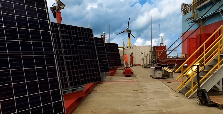
Supplying a bespoke solar power system for the South Ndola wellhead platform to support safe, reliable offshore energy.
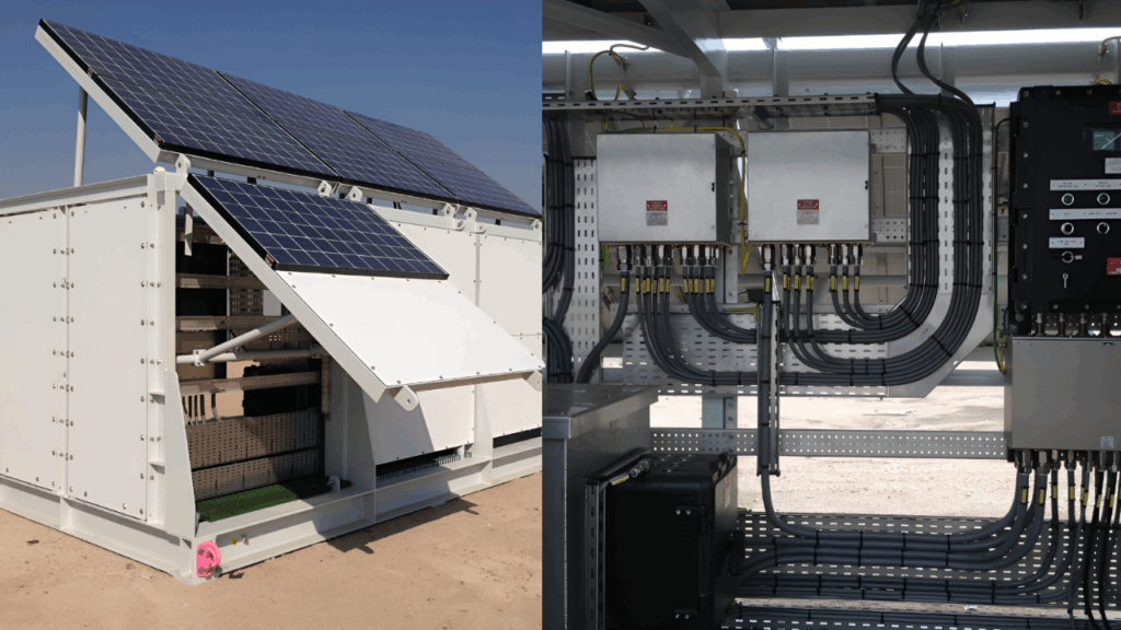
Creating a Zone 2 certified solar power system to deliver safe, sustainable energy in hazardous offshore environments.
Developing a containerised hybrid power system to support critical operations with lower emissions and improved fuel efficiency.